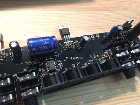
Some tips and notes on how i built my TR808 clone, the marvellous Yocto 808 project!
Buy the kit and subscribe to the forum here: http://www.e-licktronic.com/en/content/25-yocto-tr808-clone-tr-808
 I do not think it is a difficult nor long build – i spent a couple of hours on every day off from work on it, for about a month.
The excitement of being able to own an 808 drove me, and gave me the needed focus and patience boost.
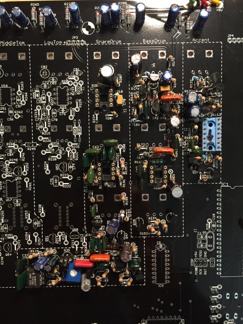 When building the Yocto, it is very important to measure every component before soldering it.
I decided to buy the resistors needed each time I was going to start a new section. This relieved me from measuring hundreds of resistors in one tiring session, putting them in order all at once, etc.
I bought a paper note book on which I would position the components, writing down their value and taping them, as I prepared for each part of the build. This helped me double check them before and while soldering them to the boards.
 I decided to socket all the IC’s and the noise section transistor.
The germanium diodes provided in the half kit are rare, treat them with care. I cut the curvy terminals to have a straight lead as per this picture.

Check the pictures I am posting here to note certain ic’s position.
I made the mistake of putting all the pots at the end, do not do it, it is a mess. Just follow the build guide-do it as recommended, at the end of each section.
Remove the encoders’ tabs before you solder them in!
 cut this part of the two encoders and the tempo pot
Please note that you do not have to cut the lead cables at the end of the build (i did it!), what Vincent meant in the last paragraph of the build guide is, you can make them shorter.
I had some issues with the flat cables, aka they broke, so i socketed them too. It is advisable to have a suitable enclosure ready before you get to link the two pcbs with flat cable, otherwise having the boards moving around will cause them to break. I would recommend you to buy this brand and sku: TE Connectivity-fsn-3a-10-3″ ribbon cable. They are the best. I socketed the connection point as per picture here, and i just slid the ribbon cable in the sockets-it works great.

Usually the boards sit a bit shallow in the enclosures, do not use led covers and cut LED leads so that mounted, they rise about the height of the sequencer’s coloured buttons.
Use 5mm spacers to lift the board up and have it sit properly, the keys will stick out properly through the holes.. i would suggest you buy a set of various spacers and screws etc that can be found on Am*zon, they come in their little handy boxes and experimenting with those will allow you to mount your precious yocto properly inside the enclosure.
More on that further down..
(see pic at the top of the post)
A few more tips to build the yocto, not a mod guide by any means, more like a ‘watch out for’ list, for instance where to look if you would like to change the value of some resistors to change the tuning of the instruments.. and other useful things to know as you go along.
A lot of these ideas are to be found in the yocto forum, but here is whatever I found essential to complete the build without headaches.
For a more in depth mods’ list, google dsl-man yocto.
Side note: please take note of these mods that allowed me to fine tune my build-i am not implying that these will be needed for your build, but keep these in mind:
Hats noise filter: for R58 use a 1K trimmer, multiturn
Cymbal noise filter: R56, use a 1K trimmer, multiturn
Cymbal decay: R93, use a 470K trimmer
Clave filter: R322, use a 20K trimmer
Clave decay: R313, use a 470K trimmer
SD noise filter: R202, use a 50K trimmer
TM1 and TM2 better adjustment range (Cowbell): at R44 put a 100K (or 56K if needed, see below the cymbal section) resistor, R45 put a 68K.
I put them on a veroboard or two, see at the bottom of the guide..
Also make sure you have many SC828 transistors to choose from for the noise generator!
THE NOISE SECTION
As opposed to the building guide, a more effective functionality of the noise generator can be achieved with this mod, as per the official Roland service manual (page 15):
R 129 use a jumper instead of the resistor listed
R 131 100k
R 127 10uF electrolytic: see this pic for correct orientation (positive side left)

R 130 22pF in parallel with resistor 130 (it means on top of the resistor, using the same soldering points – check the pic, i soldered it on the other side of the board)
I socketed Q35 as it is a very substantial part of the noise generator. Remember that for the noise section to work properly, 2SC828 transistor’s hfe must measure more or equal to 300.
NOS and new production 2SC828 values are all over the place, but ultimately you will realize most of them have a hfe thats lower than needed. Buy different sets from different sellers and take your time to measure them. Get your PEAK transistor tester out and measure them.
It can be time consuming, that’s the reason why Roland had them selected by the producer.. when stock finished, 808 production ceased-sometimes a 2SC945 was used as noise transistor. 2SC828‘s noise is grainy, as opposed to other transistors. There’s this mystique surrounding the selected transistors used by Roland, the same procedure has been used for the TR606 and CR8000 noise transistor-they were selected and are easy to spot if you would see a gutshot of said machines because the transistors have a white painted top. But remember: they are nothing special-they are just transistors whose hfe fall into range with the noise circuit. Dig into them and you will find one or two that will have the right specs.
Hfe lower than 300 will result in duller sounding, shorter decay, drier snare.
ACCENT
C 27 1n2 for 1ms pulse, needed for an effective accent
BASS DRUM
R 165 tuning resistor
SNARE
R 234 47k (positioned in the Low Tom section)
R 188 check its position carefully
R 195 tuning resistor 1
R 196 tuning resistor 2
R 202 noise filter resistor

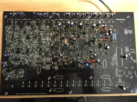 LOW TOM
R 231 to lower pitch, use a 4k7 resistor (or increase value to lower pitch)
MID TOM
R 257 tuning resistor
HI TOM
R 284 tuning resistor
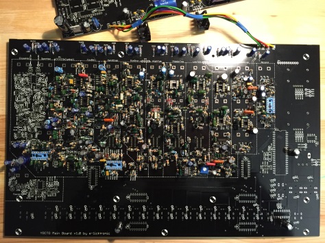 CLAVE/RIMSHOT
R 312 tuning resistor
R 315 tuning resistor
R 334 and
R 373 are part of the Hand Clap circuit, although they are to be found here
HAND CLAP
R 342 and
C 137 may have a solder bridge, it is ok
Do not rush to solder the BA6110 ic, it is better to socket it and add it at a later time, please check the picture here to have it positioned correctly.
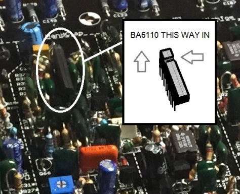 COWBELL
R 63 decay resistor 1
R 65 decay resistor 2
The sound of this trademark instrument will be tuned once you get to the cymbal section, also please note the resistor values as pointed further up on the post.
CYMBAL
Look at this section before trying to find the position of the components. It is L shaped.
R 56 noise filter variable resistor 1
R 58 noise filter variable resistor 2 (this is in common with the HiHat)
C 6 and
C 42 and
C 44 and
C 46 I did not have any 22nF caps in my stash so I used, 27nF instead.
This is the only section where it is mandatory to have a scope at hand-to tune the cowbell sound, using the two trimpots TM1 and TM2.
I used a Hantek 6022BE computer based USB scope.
Use one channel-probe on R44* resistor like this:

And ground crocodile on the above pot post like this:


Above: rotating slowly the trimpot, the values you want to see are 1.86mS, 526-540Hz and below, this wave:

If your trimpot cant get within range, change R44*. I had to lower its value to 100K first, but 56K finally got me in the range!
Time to probe TM2, like in the picture here, always grounding the nearest pot post too:

And the values you want to see, rotating carefully the variable resistor are: 1.25 mS, 800Hz:


And thats’s your cowbell sorted!
INPUT OUTPUT BOARD
Please note the position of IC4 on the i/o board..
IC4 is a optocoupler, 6N138 and it controls incoming midi signals, so if your yocto 808 has got any issue with midi like it will not sincronize to midi in, change this IC, maybe it would be better to go for a beige original:

 Before you put the keys in, make sure your enclosure will let them stick out properly (as stated before, they sit a bit shallow), and use spacers the right height to suit your eclosure.. As described here..
Before you put it in the enclosure
Prep the enclosure by screwing the spacers in the front panel- i used 5mm spacers but 10mm spacers’ screws (aka the ones that came with the mouser order) that go in for like 3/4 of the spacer’s lenght. Screw the top panel side all the way in through the spacer.
Please note there are two sides to the spacer, one is hollow and the other flat. You want to have the hollow part as receptacle to screw the pcb side in (aka at the back of the front panel) as much as you can (it is not much, a few mm’s but that will suffice to have the pcb steady in place). This means, flat side of the spacer on top.
Look at the picture:
 top panel screw: screw the spacers in flat side up, hollow side down
Nuts of the two encoders will have to be placed on top of the front panel not below.
My Yocto fired properly first off.
I made all the trimmer’s adjustment upon finishing it.
I am very satisfied by the result. Vincent has been very helpful too, and the YOCTO forum is an invaluable resource.
 Thanks Pawluk for the sturdy enclosure!
 Also, if you feel inclined, i would suggest you add a little daughterboard to fine tune the noise generator, to allow for correct voicing of the snare, hats and cymbal (check out the relevant resistors above and swap them with trimmers)..

I arranged them on a small veroboard and i am very happy with the results!
Lately (2019-2020) an unofficial custom firmware boasting amazing features as found on the original 808, such as instrument TAP writing, prompting users to update the ATMEGA ic.
For people who are modern pc challenged like me, i made a quick guide that you can find at this link:
Basically it boils down to installing the bootloader onto an ATMEGA as per Vincent at Yocto’s E-Licktronic page, and then uploading the firmware using midiOX.
I encountered issues doing so using multiple programs to transmit midi, ultimately finding out that WIN10 wouldnt allow me to do it, while under WIN7 it came out successfully!


