Category Archives: audio

Akai S1100: installing a ZuluSCSI and a new MEANWELL PSU+ZULU SD card walkthrough

Akai samplers are massive in more ways than one

Akai S1000 and its successor, S1100, are the best Akai samplers ever. They deliver a nice and punchy sound with a pronounced mid range, making drum sounds (for instance..) sit preminently in a mix.

I am using them a lot these days, making beats-based music, preferring them over the S612 and S900 for the more focused character. I decided to install a ZuluSCSI SCSI hard disk simulator so that files are handled more easily than using floppy disks..

ZuluSCSI SD card installed and ready to go

Zulu SCSI: GETTING THE SD CARD READY

WHAT SD CARD to use in the ZuluSCSI? Easy. ANY new hi speed sd card. I purchased a 32 Giga Sandisk.

https://github.com/ZuluSCSI/EmptyFileCreator-win32/releases/download/1.0.0/EFIC.zip

FORMAT THE CARD: Download Translator 7 free from Chicken System’s website. You must be connected to the internet (ok it’s 2023 guys 👀) to use it.

https://www.chickensys.com/downloads2/translator.html

Do this:

ZuluSCSI SD card formatted in FAT32 ready

INSTALLING THE ZULUSCSI

ZuluSCSI: i purchased mine here:

https://www.ebay.it/itm/364149693353

Super helpful and connected seller, cheapest EU price and he’s got a direct shop that sells ZuluSCSI, accessories for the Zulu, quality LCD screens, new Meanwell power supplies for the Akai and other samplers here:

https://studio-services.de/en/

It is very important you get the dedicated flat cable from him too-this way you will not blow your Zulu if you plugged it reversed (there are reports online of similar horror stories!). On the Zulu there’s an indication for the two pins 1 and 2. On the Akai SCSI card inside the samplers theres no indication at all.. by the way the top two pins on the vertical mounted Akai card are 1 and 2.. still the connector has a nose that has to be fitting correctly to the receptacle to make a solid connection so you better take the right cable from the seller.

The ZuluSCSI gets power from the flat cable-you dont need any extra wiring. Although there is a micro usb and a male crimp connector, you dont need them for your Akai. Leave them alone. Just the flat cable is needed.

Red stripe=pin 1
Pins 1 and 2 are silkscreened on the ZuluSCSI RP2040 (top right)
Thats your SCSI connector inside the Akai.. plug the flat cable in. Pins 1and 2 are the top ones.

Switch on the old behemoth and he will duly see the new SCSI hard disk.

Press FORM to format the virtual hard disk
The hard disk will then check for bad tracks. Just SKIP-it’s a waste of time.

All done.. you can now use your virtual hard disk. You will notice saves are LIGHTNING FAST. So there are a few pros to living in this horribly commercial music junk era.

I placed the Zulu vertically just to the right of the floppy disk drive using a couple of plastic self adhesive spacers-but they also sell covers to lodge it in the floppy drive’s place: they are cute and they have a receptacle to switch out sd cards easily.

POWER SUPPLY REPLACEMENT FOR THE AKAI S1100

These units have been used extensively and intensively in pro studios so the power supply of my second hand sampler was in urgent need of replacement. Ok, i decided to change the power supply for a new, more efficient one.

WARNING/DISCLAIMER: in this article i am going to describe operations that involve working with high mains voltage that could be LETHAL. It could KILL YOU. Let a professional do this kind of service for you. This is not a guide for the unexperienced. A focused state of mind when I undertook any of the actions described herein has been vital, as well as mandatory precautions such as wearing an antistatic vest, working on the sampler only when switched off and with the mains cord disconnected as well as procedures like having myself physically static discharged were followed strictly, so please do not undertake replacing the power supply if you are not used to work with mains voltage electricity. Remember: IT CAN KILL YOU. I shall not be held responsible for any damage of your sampler or any death/ wounds/ hurt to people using this article as a walkthrough to repair/service their sampler. This is just how i did it, it’s a blog post, so DO NOT USE this article as a guide.

The S1100 uses three separate voltages: 12v for the analog section, and for the digital section 12v and 5v. This article shows how i went about replacing the digital section power supply using a new transformer going from mains voltage (220v via the iec three pronged terminal) to 12 and 5 volts: the Meanwell RD-85A.

👆🏻Meanwell RD-85A power supply spec sheet

First of all, i switched off the sampler, disconnected the mains plug, and watched inside.

I highlighted the parts that i was going to use to wire the new power supply in: on top, the two mains INPUT; the lower header of four wires are the OUTPUT voltages going from the power supply to the boards

Mains disconnected and unplugged it was time to remove the old power supply.

I unscrewed the bottom and the two left hand side of the chassis screws to let the old power supply and its tray free and removed it carefully without touching the bottom of the pcb or the capacitors.
The old psu.. had to go.

Next, it was time to get down to the actual business.

These go from the mains voltage to the power supply input.. CAREFUL!
Push the tab underside to free the header to dislodge the mains input

I decided to use the wires already on board, so i marked them with stickers for reference of what goes where..

OUTPUT wires from the Meanwell to the boards. For colourblind people: on top, the red is the 5v, the lower, orange wire goes to 12v.
Mains voltage INPUT: N is white, L is red.
Reference pic indicating the actual terminals on the Meanwell.. DO NOT mix the input mains voltage red wire L with the output 5v wire.
I snapped the wires as close to the crimped header as possible and put some terminal friendly lugs, insulated with heatshrinking tubes.
I screwed the wires to the terminals.

All grounds are to be linked, bridged together, and they all go to the chassis ground. Since the main chassis ground is a secure, glued screw whose nut is unmovable, i decided to use a metal spacer and couple of screws to create another chassis ground, and checked for continuity with the the other stubborn dude using the multimeter’s buzz feature.

Alternate chassis ground, checked for continuity with the official one, that sits at the bottom of the machine in parallel with the IEC mains terminal, bolted to a nut.
Blurry pic of the main chassis ground point.. note the green glue.

Because the power supply needs a minimum load to operate correctly, two resistors are needed across the voltage and ground of 5v and 12v, as mentioned in this tread on Gearslutz 👎🏻

https://gearspace.com/board/electronic-music-instruments-and-electronic-music-production/1132743-recap-powersupply-your-vintage-synths-samplers-akai-s1000-blowup-3.html

These resistors are put one each between voltage and ground at the 5v and 12v terminals. Please note how i bridged the leftmost COM to the main GND on the Meanwell: all grounds are in common.

Massive looking 50 Ohms 50W resistors: USELESS

For my first test, i used a couple of 33 Ohms 10W to apply a minimum load as suggested on Gearslutz but one of them was BURNING HOT; i tried 50 Ohms 50W too and still one was overheating, so i replaced both with a 47k 5W (you will see the picture down below): MUCH BETTER!

FIRST CHECK: voltages. Without connecting the outputs, i had to see how the psu was working.. Now i had the resistors in place, i checked for continuity between all grounds and the chassis grounds, and plugged the mains, turned the power on (the IEC is connected to the sampler on off switch) and took some readings of the psu, loaded only with two resistors across the output voltages.

Checking the 5v output: nevermind the 33R resistor, read above
Not too bad
Checking the 12v output
Looking good..

The trimmer on the right hand side of the Meanwell terminals can be used to adjust the two voltages (5v and 12v).. it’s a give and take science between the two outputs but in the end i had some good results.. 12v measured 12,6v and 5v measured 4,6v-the sampler works great with no overheating resistors inside!

A final test had to be carried out with the outputs in place. The moment of truth. I connected the 12v and 5v outputs to the Akai.

Thats it.. the whole shebang.

Upon switching the Akai on, all went well with some minor adjustment to be done using the trimmer: the load had changed the voltage readings sensibly, but thanks to the two resistors all went down as expected.

Next it was time to switch everything off, unplug the mains and find a way to fit the new power supply in the case.. i used the power supply original tray to hold it in place using the same screws on the bottom and side of the unit, and some wire holders, wrapped between the psu grille and some of the tray holes.

You can just about see the wire holders (green) at the bottom there.

Akai S900 disk drive replacement

Since keeping it strictly old school is a must, i decided NOT to go the Gotek/ HxC floppy drive emulation route to make up for my S900’s broken floppy disk drive.

Which disk drives can be used to replace the Akai S900 floppy drive? Theres a page on gearsluts with a few suggestions, but i felt the info was a bit messy and not really clear (a few yes this works, some no-nos etc).

I took an old amiga 500 external floppy disk drive and yes it works on the akai S900-just be careful about the header’s orientation. It is a drop in replacement. It can format and use modern HD floppy disks too.

So in a nutshell: amiga 500 floppy disk drives can work as a replacement for the Akai S900 sampler.

Just a piece of info from Masu.

RE303 TB303 replica building tips

The RE303 project is an amazing one-man effort to diy the Roland TB-303 Bassline to the extreme- starting with a cloned PCB of the original, and with a lively forum of rare parts being offered, recommended, sold and traded to make a 1:1 copy of the 303 (well, at least the circuitry).

Given the rarity and price tag associated with the original item, it should be of interest to anyone who’s a fan of Roland’s illustrious past.

I plunged into this project because i love acid house and its main voice, the TB303. I associate its sounds to the words “pearl”, “drop”, and the adjectives “wet” and “chirping”.

As anyone reading my blog already knows, i own a couple of x0xb0xes but neither of them had that “pearly” sound.

Cue the beginning of Phuture’s “Acid Trax”. The bassline rises from what seems to be white noise, a shash of the volume pot being slowly turned up.. the real TB303 must do magic stuff like that.

This is considered hardcore diy but really, it is hardcore part sourcing- you can choose how close to an original, you want it to be. I used a mixture of carbon and metal film resistors, whereas the original only sported the carbon variety.. most people go for the all-carbon build, just to give you an idea of the scene.

Ok, i bought the Space Cadet kit from dinsync.info and it arrived from Sweden in a low profile box, the pcbs wrapped in egyptian hyeroglyphics printed paper, very trippy. Also included are a couple of rare transistors, the pots, a Sumida coil, the bare rare basics.

Shopping:

-first of all i ventured out to buy knobs, buttons: syntaur.com, ebay

-rare transistors: the forum, more ebay action after a fake parts scare brewing through the forum with parts being measured, pictured and compared.

One user also measured all his TB303’s transistors and wrote down the hfe: ch-ch-ch-check it ooout!

On the RE303 forum, there is a link to a Mouser cart with all the non rare stuff, but since my local retailer has got quite a good selection of vintage stock (1980’s), i decided to shop local and save on Mouser’s over inflated shipping and handling costs.

-Enclosure: on the forum it is offered in metal sheet, with fully customable graphics, or the “official metal case” with dinsync.info and RE303 logos, the mandatory plastic puzzle like cad template is also present..

This guide adds just a few tips to the already thorough building manual-stuff that has been replied on the forum or that i found out myself (not a lot).

If it’s not there, it should be here!

To build this i used a 35w cheapo soldering iron, just keep the point clean at all times, non rohs-approved solder, a cheap chinese diy oscilloscope (i bought it prebuilt, or as the ebay buy it now listing said, pre-“welded”), my Atlas Peak transistor tester, a simple DMM. I measured all the parts before soldering them to the board. I socketed all the IC spots.

Using the official enclosure?

Do this:


to the switches pcb first of all- make sure you dont cut the ground line!

2017 03 05 305
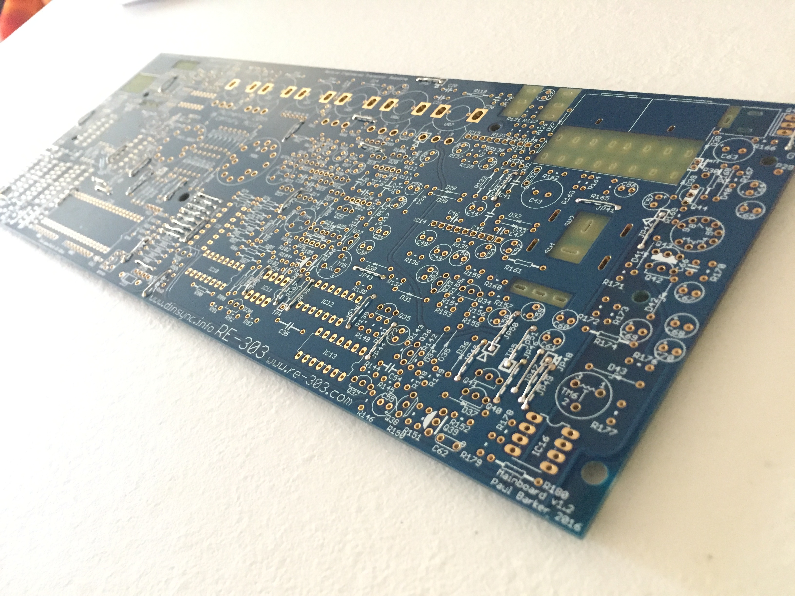
First of all you must install all the wire jumper. Tedious as HELL and you are going to lose your sight. There are two-three size jumpers. Quick tips using a typical cheapo ikea toolbox pincer for the most common sized jumpers:


Power supply section notes: use a nice and heavy switching (aka regulated) power supply/ ac dc transformer, centre negative. That way you wont burn yourself if you happen to touch the power transistor (it happened to me!).

Before you do anything, take a picture of the unpopulated pcb and print it. This will serve you as a guide to track down the position of so and so components, orientation of diodes and electrolytic caps, etc anything that once built, will not be easily readable-and you are going to need it once the built is over and you are going to need calibrating or (hopefully not) troubleshooting.

Build the power section after fitting the preliminary parts and all those jumpers (they are a lot and if you have an issue locating some of them, either look for some hi res pics @ the forum or, just leave it and you will find them as you go).

Some people like to put coloured tubing to the jumpers to add a nice lively effect to the build, i chose not to but it really is a nice idea. The trending colour is yellow as of April, 2017. 😊

Follow the official guide closely to measure and make sure the voltages are correct.. if you are having issues getting the magic 5.333v at TP5, you will have to “play” with R174, aka sticking a 4k7 resistor in parallel with it to lower its resistance. I soldered the 4k7 at the other side of the pcb. That gave me more play to dial the required voltage using the trimmer.


Build the VCO..

I have a 500R PTC tempco, as per original, but it did not fit the pcb with the components populated-i soldered it at the back of the pcb, shrink-tubed.

Make sure you have a few different brands’ 4066BE in case your final build sounds wobbly on slides and accented notes.

2017 04 02 199

Here’s where that elusive D25 goes..

The pads in this section are very close.. if you check the schematic, you wouldnt worry too much about it, some of them are connected! For these you will need a tighter tolerance, 0,1% resistors.

(Please note the original had carefully chosen 0,5% tolerance resistors in this spot).


Do not forget to mark the parts going into those sockets and the IC orientation..

I used, 1N914 diodes instead of 1N4148 there-dont ask me why I did, but they should be pretty much the same.

That 303 ‘squarish’ wave through my cheapo unmodded chinese oscilloscope..

To check the waveforms, use the outmost pin of the waveform switch (ground) and the middle pin (positive).

Build the filter.

If should need a reference of how the transistors are oriented in this section, there you go:

Please note how i socketed the trannies of the filter section, it might be interesting to swap them later with different ones (as it happened, the 303 had a few revisions and the filter section uses transistors as diodes, so you may actually hear a subtle variation of its sound caused by the different transistors used).

This is also where the trimmer TM3 is (you will come back to this later when it comes to tuning the 303 properly).

To check the resonance, use this pin (aka TP6) of the pot-the furthest to the right. When you solder this specific pot, make sure it is aligned with the others.. look at how the pots sit from the side before soldering its six terminals. The rightmost pin is TP6, one of the testing points of the 303. Where is TP6? There. Remember.

Build the envelope section

Space Cadet kit, ENV pot measures 1M ohms.

Build the VCA

Remember that the negative pole of the tantalum capacitor is marked on the pcb.

Remember Q31 is not marked on the silkscreen.

Please note the ‘1’ mark, on top of R125, that signals the appropriate BA662A (aka ic15) pin 1 alignment.

Make sure you solder the two trigger jacks before you fit cap C37 to give you an idea of the cap measure you should use if you are not following the mouser cart..

Remember: at any time, these cv and trig are OUTbound signals.

Once you have all the i/o jacks fitted, you will get your mind blown by listening to the sound of you RE303 for the first time upon testing your work so far accomplished.

Digital section

If you cannot find where they are, R181 is the one needing a bit of tubing, R182 is the to the left of the DIN socket pads.

Solder the selector and time pots with the pins aligned to the pads holes-they must not surface the back of the pcb! Try to solder them as even as possible.


If you are using the Sonic Potions CPU (like i did), just remember to leave out the ics as per the CPU’s installation manual.

The CPU will have to be fitted to the proper sockets: check this pic.

2017 04 01 417

Rare part: the DIN sync jack.. I found it locally, from my retailer!

I had to remove the two innermost pins (it’s a double switch) to fit the pcb pads.. here’s what it does: when you plug a din sync drum machine, the internal sequencer timing is turned off and the TB303 is synced to the master DIN.

Two pins must be clipped off..But it fits perfectly!

I like the idea that my RE303 is powered by Philips.. 🙂

img_7109

Please remember, if you are using the RE-303 official case, you will have to solder the midi dins directly to the SP ic.. just rock the molex male back and forth until it breaks and.. Bob’s your uncle.


Buttons/switches section.

Please note how i had to bend the transistors-i subbed the original miniaturized transistors with 2sc1310 (310) for the 2SC2603 but the SA115 could not be substituted-i tried to but experienced crazy behaviour on the keyboard..some switches were not working, etc

The silkscreen shows only the emitter mark of the transistors in this section.

2017 04 02 232

I used shrink tubing cut to measure instead of the 6mm high led holders.

Due to the space constraint dictated by the height of the CPU sockets, I soldered the HD2 wires to the top of the switches PCB.

The wires linking the two pcbs have been wrapped with paper scotch tape in a flat cables fashion.

Later i removed these and switched to very functional flat ribbon cable from TE Connectivity (part number FSN-23A-20 for 20 pins, i then cut them to the needed pin count).

And.. ready!

x0xb0xes: made in China, Germany and USA

Ages ago i bought my first Mode Machines x0xb0x from Touched by Sound in Germany. They were the first fully assembled x0xb0xes on sale here in Europe and hence they have been reviewed a few months later on Sound on Sound. They came with those horrible looking MC303 knobs, but the idea of having a fully operational, Bassline clone with onboard sequencer was embarassingly exciting. In 2017 all this has changed, since the advent of the RE303!

From the description given to me by TBS and the sticker on mine, they indicated that they were Made in Germany.

One year later Mode Machines came up with the x0xb0x mk2, this time “guaranteed” to have been made in Germany. 

Would this second statement imply, mine was actually made somewhere else other than Germany, EU?!

Today i decided to pop my Mode Machines x0xb0x open and have a look inside.

The machine itself, sounds good but it loses more of the lower frequencies than it should as you turn the cutoff and resonance up, but it sits nicely in a mix because of this and it is quite squelchy.

Now on with the gutshots:

Dirt on the pcb, almost like corrosive traces of handling, etc

Components scattered on the board and soldered, clearly assembled as quickly as possible.

Grey looking solder joints. I dont know if rohs approved solder is supposed to look like this but it’s not shiny, they look almost like cold solder joints.

Rubycon electrolytic caps.. part of the standard kit i suppose..

More traces of handling.. dirt..
All in all, the only other example i can think of of a pcb that bears the same, corroding handling marks, grey solder joints and cowboy assembling like this, is my chinese made, battered components sporting, bog standard, cheap as hell, barely working, terrible looking digital oscilloscope. They even smell bad, the same way.


My personal feeling: my Mode Machines x0xb0x was really either made in China or made in Germany by hurried chinese workers in a very dark and unpleasant cabin.

BUT: it sports original 536 transistors, that give it a very impressive TB303 character! 

Sometime later, i got my hands on a NY made, x0xb0x from x0xs0urce: a whole different story.

Rounder sound, red leds instead of purple ones, and check these gutshots..careful assembling and soldering, etc. a work of love-mind you it costed twice the price of the mode machines..

Welcoming greenie caps as per the original tb303..

But ouch! This has 945 transistors (Roland mass production’s transistor of choice in those days)- it doesnt sound as wild as the Mode Machines!! 

Selmer Buzz-Tone

I have been building Selmer Buzz Tones for a few people recently. 

Featuring rare 2N2613 transistors on choc brown paxoline board, on eyelets just like the original. 

One small mod is the cap tuck away under the board, to give it some juice.

Cheapo build for a friend:

Another build.. featuring the Palenque astronaut..


Expensive nos carbon comp build for a friend
They all sound 👍🏿.

Hohner Basset

When i bought it it looked like this


I opened it up to clean it and realised this wasnt its original colour.


It really was taupe gray before, but the years had the plastic chassis yellowing

I decided to restore it to its original colour (or as close as i could…)

After 5 months of great fun, I had to open it up because the output went silent.

Gutshots of the Hohner Basset!

Lets start with the DIN jack that connects it to the bass amp..


Keyboard:

Circuit board and caps jungle:

Inside the white enclosure there’s a lamp and a ldr.. this assembly is the actual “percussion” section.

You press a note on the keyboard, the light goes off slowly (sustain) according to the knob position, when not in auto mode.

Video below..

Pcb: 3.1967!!

Ahem this means the caps have been doing their job for 50 long years! Only one of the capacitors has failed, please note- the blue valvo 100uF cap now measures 1uF!

Output DIN and 3 pronged jack, fuse

Video showing the lamp going off when a note is keyed.

Dynacord EC280

Was this the very first BBD delay? 

 
Tabletop machine, self oscillating AND from past internet auctions and reviews it is apparent, nobody knows how to determine if theirs is in working order (😂), because it is very temperamental and does a lot of different things.. But when it behaves, it’s magic!

Echo, reverb and has a very weird chorus.

Amazing and beautiful, nothing like a tape echo or a memory man.. Far less predictable!

A delay with character.


De La Soul Three Feet High And Rising

1989. This and Paul’s Boutique blew my mind that year.

Can you guess how many times i happily re-bought this record (the first one being the picture disc when it first came out) through the years? Same as Paul’s Boutique actually.. 😂