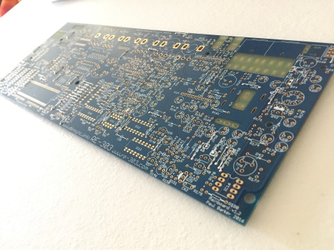
The RE303 project is an amazing one-man effort to diy the Roland TB-303 Bassline to the extreme- starting with a cloned PCB of the original, and with a lively forum of rare parts being offered, recommended, sold and traded to make a 1:1 copy of the 303 (well, at least the circuitry).
Given the rarity and price tag associated with the original item, it should be of interest to anyone who’s a fan of Roland’s illustrious past.
I plunged into this project because i love acid house and its main voice, the TB303. I associate its sounds to the words “pearl”, “drop”, and the adjectives “wet” and “chirping”.
As anyone reading my blog already knows, i own a couple of x0xb0xes but neither of them had that “pearly” sound.
Cue the beginning of Phuture’s “Acid Trax”. The bassline rises from what seems to be white noise, a shash of the volume pot being slowly turned up.. the real TB303 must do magic stuff like that.
This is considered hardcore diy but really, it is hardcore part sourcing- you can choose how close to an original, you want it to be. I used a mixture of carbon and metal film resistors, whereas the original only sported the carbon variety.. most people go for the all-carbon build, just to give you an idea of the scene.
Ok, i bought the Space Cadet kit from dinsync.info and it arrived from Sweden in a low profile box, the pcbs wrapped in egyptian hyeroglyphics printed paper, very trippy. Also included are a couple of rare transistors, the pots, a Sumida coil, the bare rare basics.
Shopping:
-first of all i ventured out to buy knobs, buttons: syntaur.com, ebay
-rare transistors: the forum, more ebay action after a fake parts scare brewing through the forum with parts being measured, pictured and compared.
One user also measured all his TB303’s transistors and wrote down the hfe: ch-ch-ch-check it ooout!
On the RE303 forum, there is a link to a Mouser cart with all the non rare stuff, but since my local retailer has got quite a good selection of vintage stock (1980’s), i decided to shop local and save on Mouser’s over inflated shipping and handling costs.
-Enclosure: on the forum it is offered in metal sheet, with fully customable graphics, or the “official metal case” with dinsync.info and RE303 logos, the mandatory plastic puzzle like cad template is also present..
This guide adds just a few tips to the already thorough building manual-stuff that has been replied on the forum or that i found out myself (not a lot).
If it’s not there, it should be here!
To build this i used a 35w cheapo soldering iron, just keep the point clean at all times, non rohs-approved solder, a cheap chinese diy oscilloscope (i bought it prebuilt, or as the ebay buy it now listing said, pre-“welded”), my Atlas Peak transistor tester, a simple DMM. I measured all the parts before soldering them to the board. I socketed all the IC spots.
Using the official enclosure?
Do this:

to the switches pcb first of all- make sure you dont cut the ground line!
 First of all you must install all the wire jumper. Tedious as HELL and you are going to lose your sight. There are two-three size jumpers. Quick tips using a typical cheapo ikea toolbox pincer for the most common sized jumpers:
Power supply section notes: use a nice and heavy switching (aka regulated) power supply/ ac dc transformer, centre negative. That way you wont burn yourself if you happen to touch the power transistor (it happened to me!).
Before you do anything, take a picture of the unpopulated pcb and print it. This will serve you as a guide to track down the position of so and so components, orientation of diodes and electrolytic caps, etc anything that once built, will not be easily readable-and you are going to need it once the built is over and you are going to need calibrating or (hopefully not) troubleshooting.
Build the power section after fitting the preliminary parts and all those jumpers (they are a lot and if you have an issue locating some of them, either look for some hi res pics @ the forum or, just leave it and you will find them as you go).
Some people like to put coloured tubing to the jumpers to add a nice lively effect to the build, i chose not to but it really is a nice idea. The trending colour is yellow as of April, 2017. 😊

Follow the official guide closely to measure and make sure the voltages are correct.. if you are having issues getting the magic 5.333v at TP5, you will have to “play” with R174, aka sticking a 4k7 resistor in parallel with it to lower its resistance. I soldered the 4k7 at the other side of the pcb. That gave me more play to dial the required voltage using the trimmer.

Build the VCO..
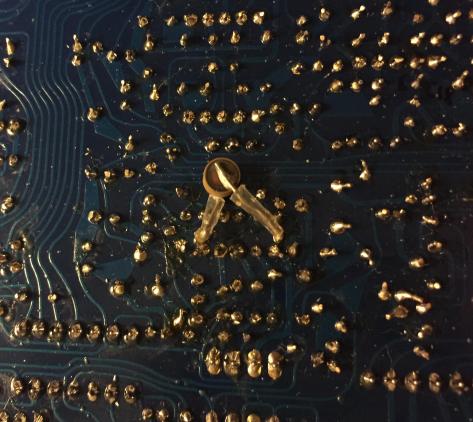
I have a 500R PTC tempco, as per original, but it did not fit the pcb with the components populated-i soldered it at the back of the pcb, shrink-tubed.
Make sure you have a few different brands’ 4066BE in case your final build sounds wobbly on slides and accented notes.
Here’s where that elusive D25 goes..
The pads in this section are very close.. if you check the schematic, you wouldnt worry too much about it, some of them are connected! For these you will need a tighter tolerance, 0,1% resistors.
(Please note the original had carefully chosen 0,5% tolerance resistors in this spot).

Do not forget to mark the parts going into those sockets and the IC orientation..
I used, 1N914 diodes instead of 1N4148 there-dont ask me why I did, but they should be pretty much the same.

That 303 ‘squarish’ wave through my cheapo unmodded chinese oscilloscope..
To check the waveforms, use the outmost pin of the waveform switch (ground) and the middle pin (positive).
Build the filter.
If should need a reference of how the transistors are oriented in this section, there you go:
Please note how i socketed the trannies of the filter section, it might be interesting to swap them later with different ones (as it happened, the 303 had a few revisions and the filter section uses transistors as diodes, so you may actually hear a subtle variation of its sound caused by the different transistors used).
This is also where the trimmer TM3 is (you will come back to this later when it comes to tuning the 303 properly).

To check the resonance, use this pin (aka TP6) of the pot-the furthest to the right. When you solder this specific pot, make sure it is aligned with the others.. look at how the pots sit from the side before soldering its six terminals. The rightmost pin is TP6, one of the testing points of the 303. Where is TP6? There. Remember.

Build the envelope section

Space Cadet kit, ENV pot measures 1M ohms.
Build the VCA
Remember that the negative pole of the tantalum capacitor is marked on the pcb.
 Remember Q31 is not marked on the silkscreen.
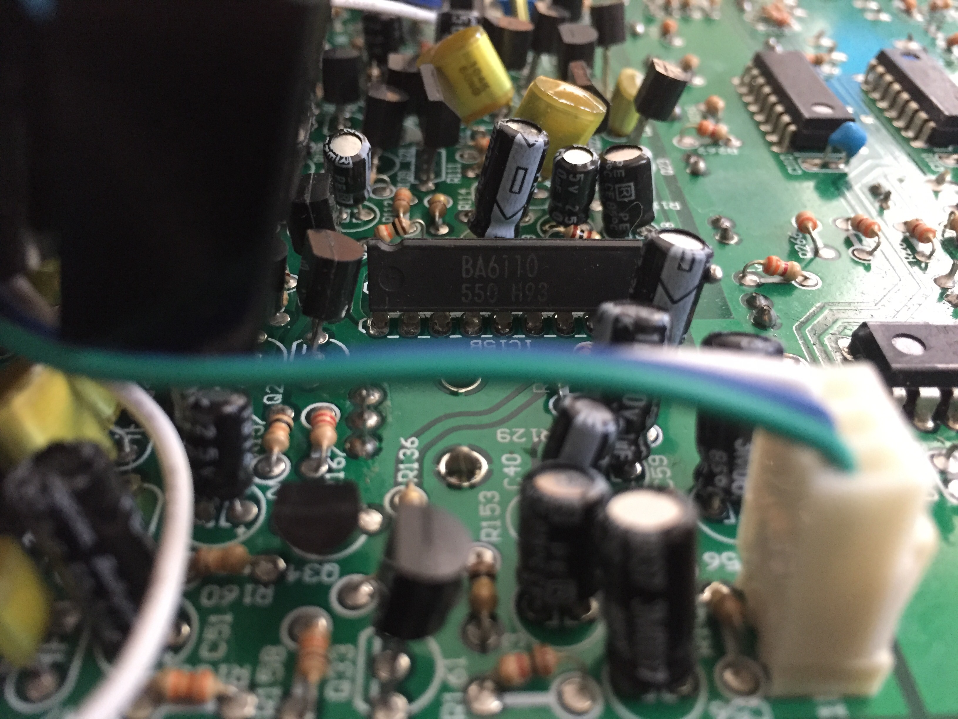
Please note the ‘1’ mark, on top of R125, that signals the appropriate BA662A (aka ic15) pin 1 alignment.
Make sure you solder the two trigger jacks before you fit cap C37 to give you an idea of the cap measure you should use if you are not following the mouser cart..
Remember: at any time, these cv and trig are OUTbound signals.
Once you have all the i/o jacks fitted, you will get your mind blown by listening to the sound of you RE303 for the first time upon testing your work so far accomplished.
Digital section
If you cannot find where they are, R181 is the one needing a bit of tubing, R182 is the to the left of the DIN socket pads.

Solder the selector and time pots with the pins aligned to the pads holes-they must not surface the back of the pcb! Try to solder them as even as possible.

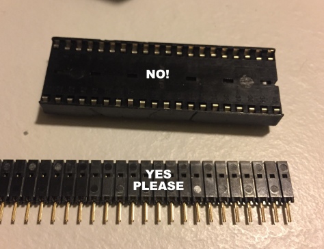
If you are using the Sonic Potions CPU (like i did), just remember to leave out the ics as per the CPU’s installation manual.
The CPU will have to be fitted to the proper sockets: check this pic.
Rare part: the DIN sync jack.. I found it locally, from my retailer!
I had to remove the two innermost pins (it’s a double switch) to fit the pcb pads.. here’s what it does: when you plug a din sync drum machine, the internal sequencer timing is turned off and the TB303 is synced to the master DIN.

Two pins must be clipped off.. But it fits perfectly!

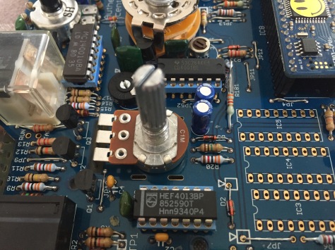
I like the idea that my RE303 is powered by Philips.. 🙂
Please remember, if you are using the RE-303 official case, you will have to solder the midi dins directly to the SP ic.. just rock the molex male back and forth until it breaks and.. Bob’s your uncle.

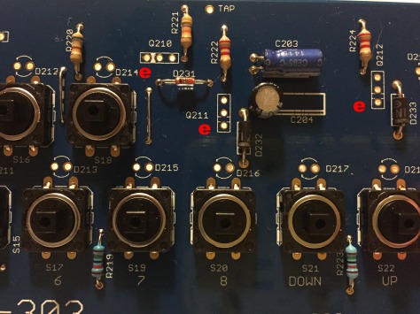
Buttons/switches section.
Please note how i had to bend the transistors-i subbed the original miniaturized transistors with 2sc1310 (310) for the 2SC2603 but the SA115 could not be substituted-i tried to but experienced crazy behaviour on the keyboard..some switches were not working, etc
The silkscreen shows only the emitter mark of the transistors in this section.

I used shrink tubing cut to measure instead of the 6mm high led holders.

Due to the space constraint dictated by the height of the CPU sockets, I soldered the HD2 wires to the top of the switches PCB.
The wires linking the two pcbs have been wrapped with paper scotch tape in a flat cables fashion.
Later i removed these and switched to very functional flat ribbon cable from TE Connectivity (part number FSN-23A-20 for 20 pins, i then cut them to the needed pin count).


And.. ready!